
Ongoing
PCB Board Gallery
Custom-designed PCB boards for our robotics projects, all created with the Python-based hardware description language PolymorphicBlocks.
Research focus
- Custom electronics
- PolymorphicBlocks
- Robotics hardware
Project story
Images and demonstrations
17 media items
01 / BALLU Gen2 PCB Board
Upgraded sensor arrays and Lora sub-G communication compatible.
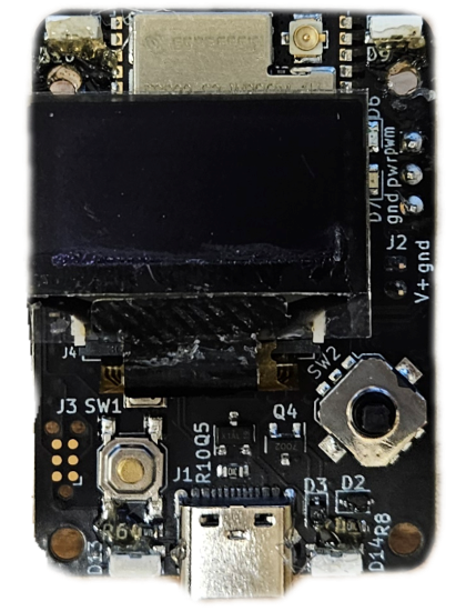
- MCU: ESP32-S3
- Sensors: 6-axis IMU (LSM6DSV16XTR), BME680 pressure/air monitor, INA219 power sensing, A31301 3D Hall-effect sensor (via expansion cable)
- UI: OLED screen, directional switch, RGB LED, red/blue LED
- Motor: 2× PWM servo
- Power: LiPo, 3.3V regulator, charging circuit, software power switch, reverse protection
- USB-C: programming, power supply, and charging
- FPC connectors: 2× 10-pin 0.5 mm-pitch cables carrying I2C, SPI, GPIO, GND, V3V3, VBATT
- 6-layer board
Change from Gen 1
- 2× generic 10-pin FPC connectors for external devices (Lora and contact sensors)
- Pressure/air sensor
- High-end IMU
- Battery sensing
- Power reverse protection
- Enhanced user interface
- 23% less weight
 01
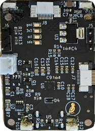
01BALLU Gen2 PCB — back
Documentation02 / BALLU PCB Board
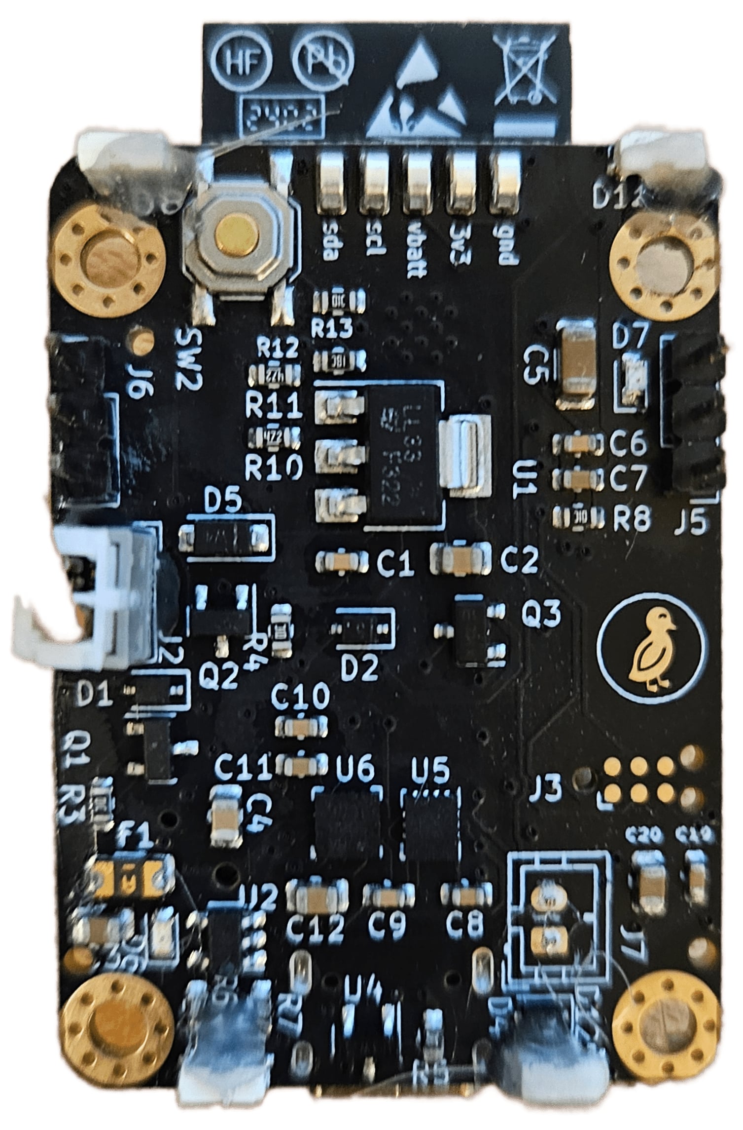
Fully integrated board that includes the microprocessor and all sensors in one board.
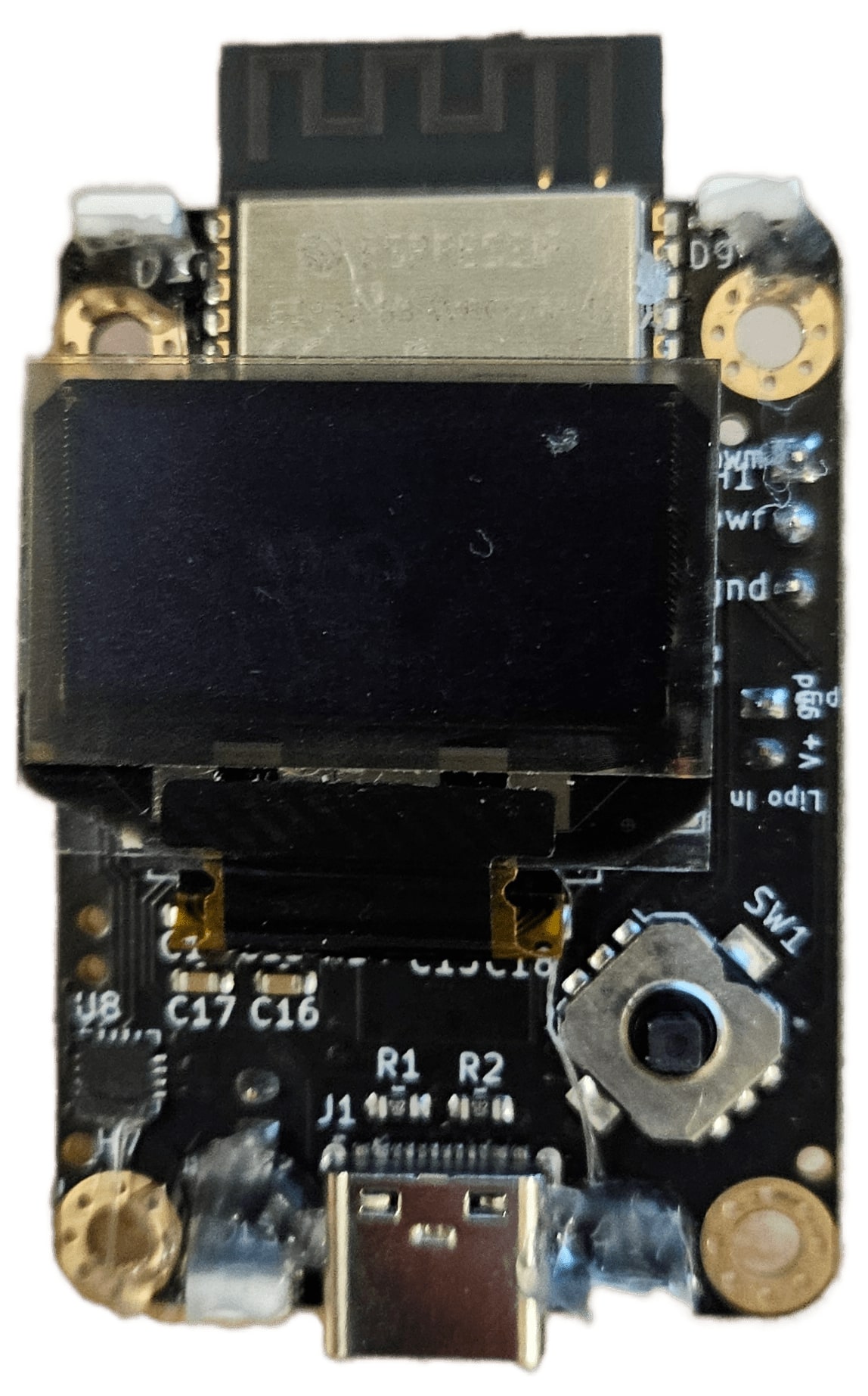
- MCU: ESP32-S3
- Sensors: 9-axis IMU (LSM6DS3TRC and QMC5883L), voltage sensing
- UI: OLED screen, directional switch, speaker, RGB LED
- Motor: 2× PWM servo
- Power: LiPo, 3.3V regulator, charging circuit, software power switch
- USB-C: programming, power supply, and charging
- 4-layer board
 01
01BALLU PCB — back
Documentation03 / Lora Sx1262 Communication Board
Lora Sx1262-based sub-GHz communication board (915 MHz).
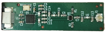
- MCU: none (paired with BALLU Gen2)
- Lora Sx1262
- 2-layer board
Special thanks to Ducky for providing the reference design and advising · Special thanks to Eric for placement and routing
04 / Lora Communication Daughter Board
STM32G4-based daughter board that adds Lora Sx1272 sub-GHz communication to BALLU.
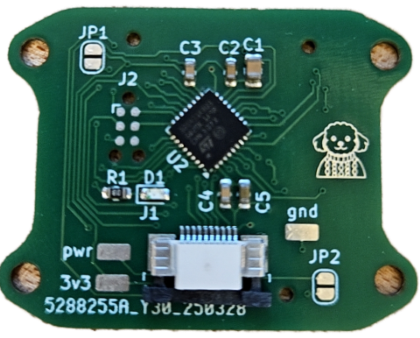
- MCU: STM32G431 (for BALLU Gen2)
- Programmer pins, status LED
- 2× SPI to the Sx1272-based sub-GHz communication board
- 1× SPI to the BALLU Gen2 board
- 2-layer board
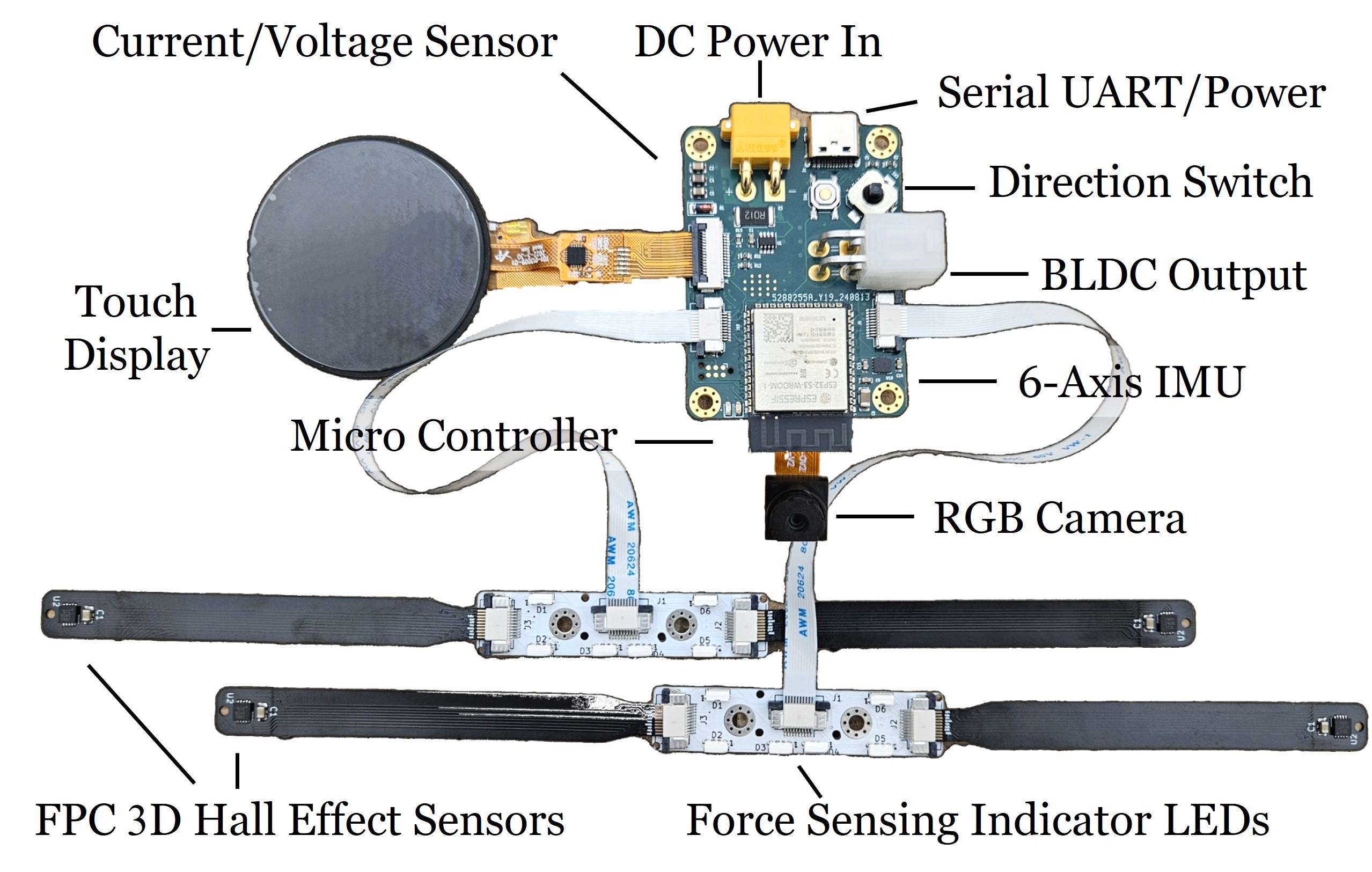
05 / MAGPIE Gen2 PCB Board
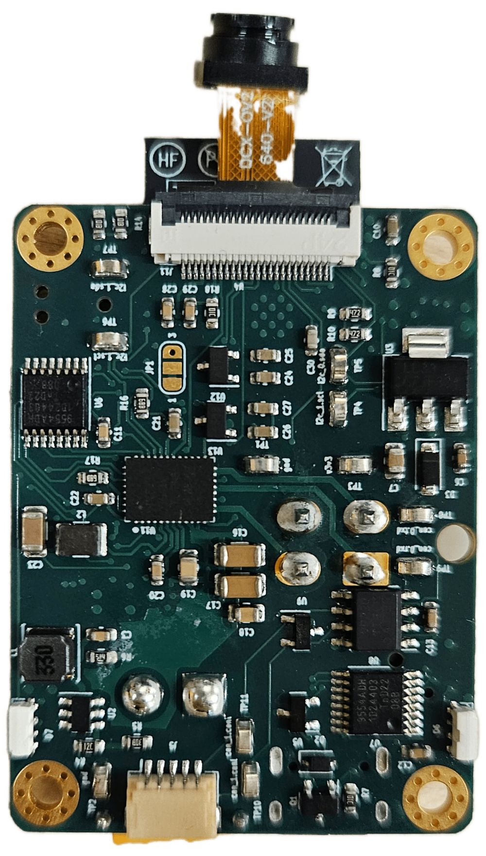
Integrated PCB for MAGPIE's 3D Hall-effect 8-axis force sensing and BLDC driver.
- MCU: ESP32-S3
- Power: USB-C & LiPo (7.4–26V) with 4.5V, 3.3V, 3.0V, 2.5V, 1.2V regulation
- Sensors: INA219 power sensing, 6-axis IMU, FPC 3D Hall sensor connectors
- Display: circular TFT touchscreen
- Camera: OV2640 FPC module
- Motor: BLDC driver
- UI: circular color touchscreen, RGB LED, directional switch
- Ports: CAN bus, WiFi/BLE, dual IO expanders, 2× FPC I2C
- 6-layer board
 01
01MAGPIE Gen2 PCB — back
Documentation06 / MAGPIE Daughter PCB Board
Secondary board for magnetic sensor breakout with contact indicators, on a flex PCB.

- Sensor: up to 2× A31301 via FPC with digital I2C addressing
- UI: 6× RGB LED Neopixel array for contact indication
- Connectivity: FPC connectors (1 in, 2 out) routing I2C, power, and digital signals
- Flex PCB with a gold finger that connects directly to the main board
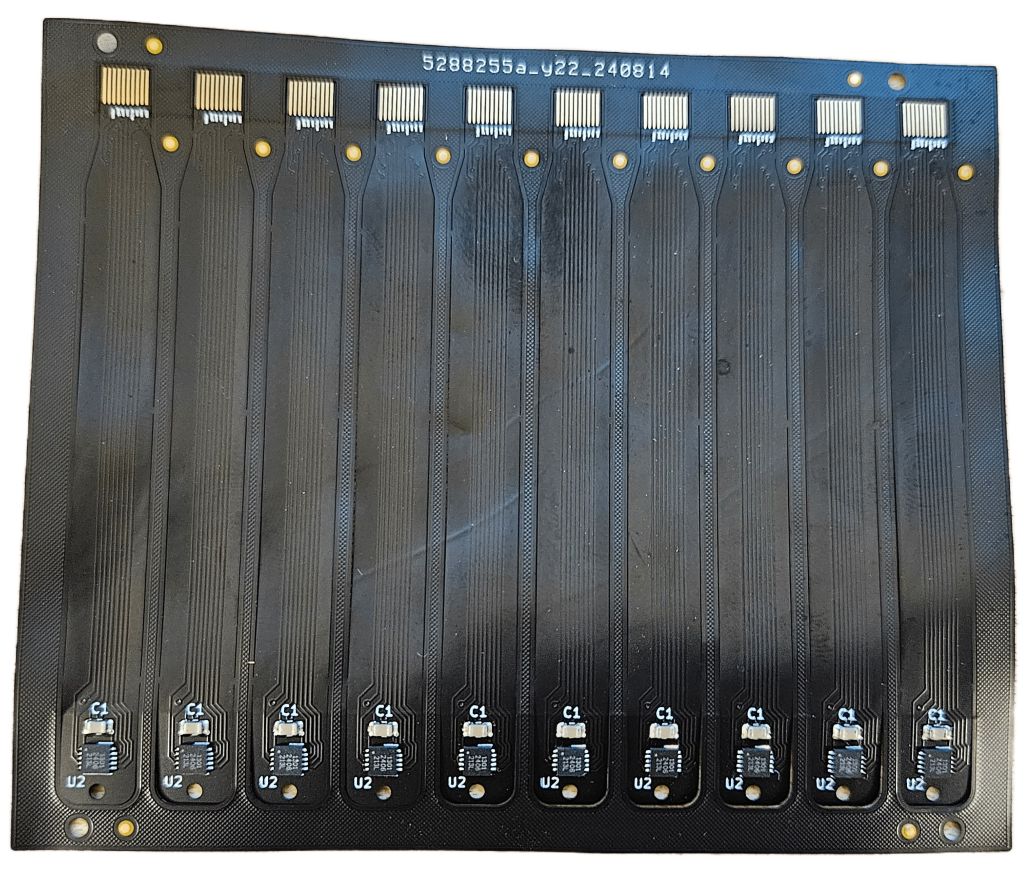 01
01MAGPIE sensor flex PCB
Documentation07 / MAGPIE Prototype PCB Board
Prototype MAGPIE PCB board.
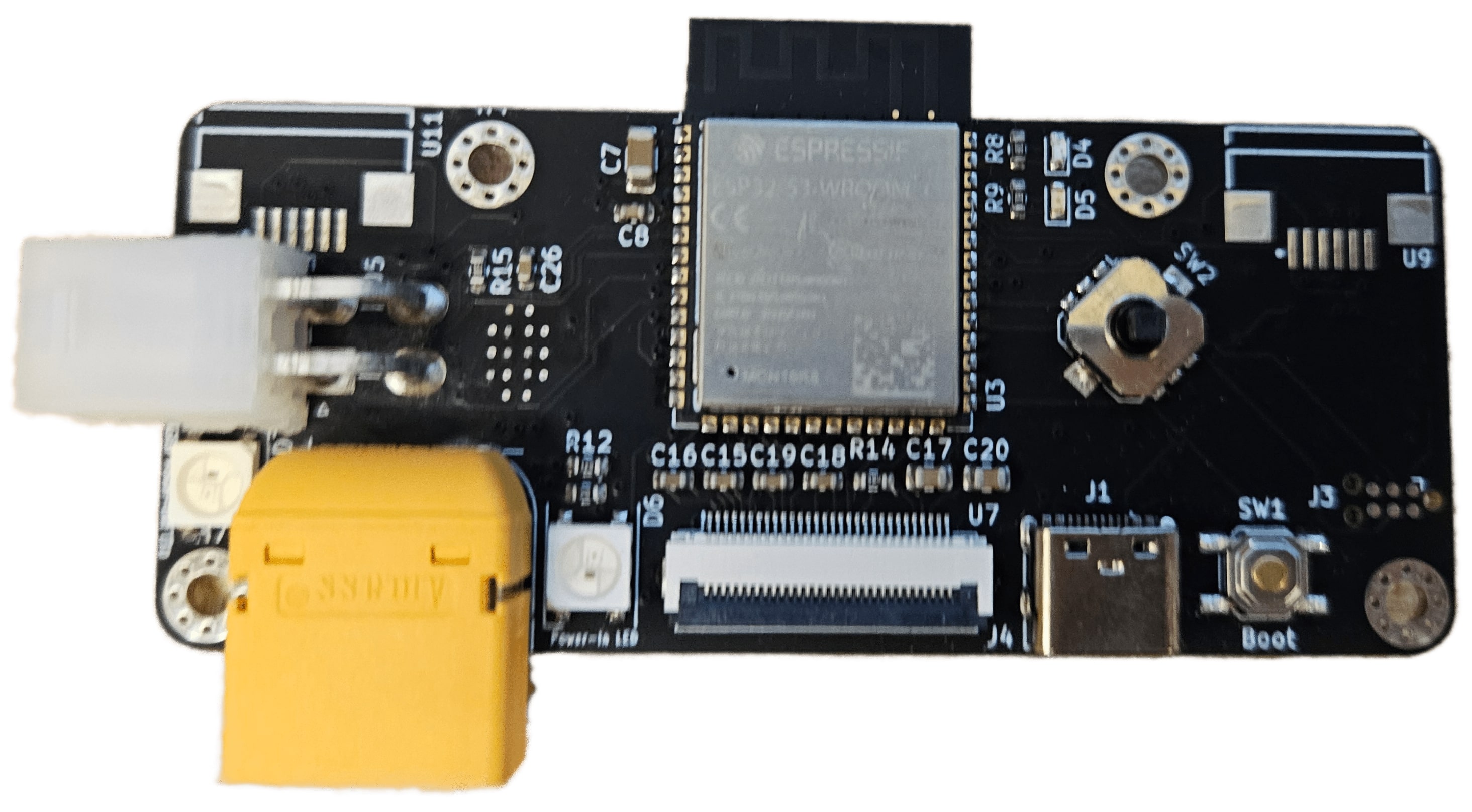
- MCU: ESP32-S3 for programming, power, and charging via USB-C
- Power: LiPo (7.4–28V) with 4.5V & 3.3V regulation and battery sensing
- Sensors: 9-axis IMU, QMC5883L magnetometer, 4× FPC magnetic sensor connectors
- UI: OLED screen, side-firing Neopixel array, dual debug LEDs (red/blue)
- Controls: digital directional switch
- Motor: BLDC driver (MCF8316A1VRGFR)
- 4-layer board
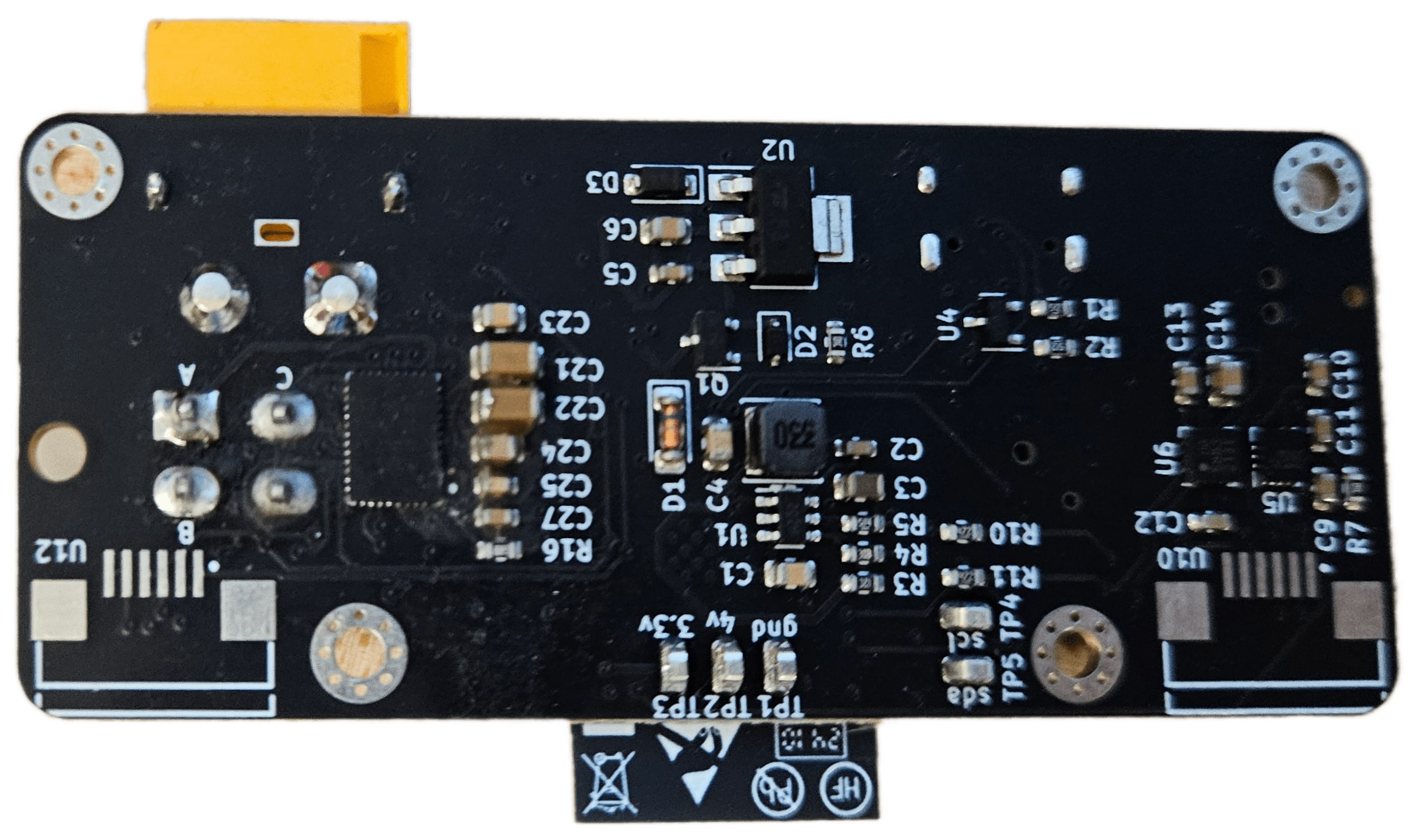 01
01MAGPIE prototype PCB — back
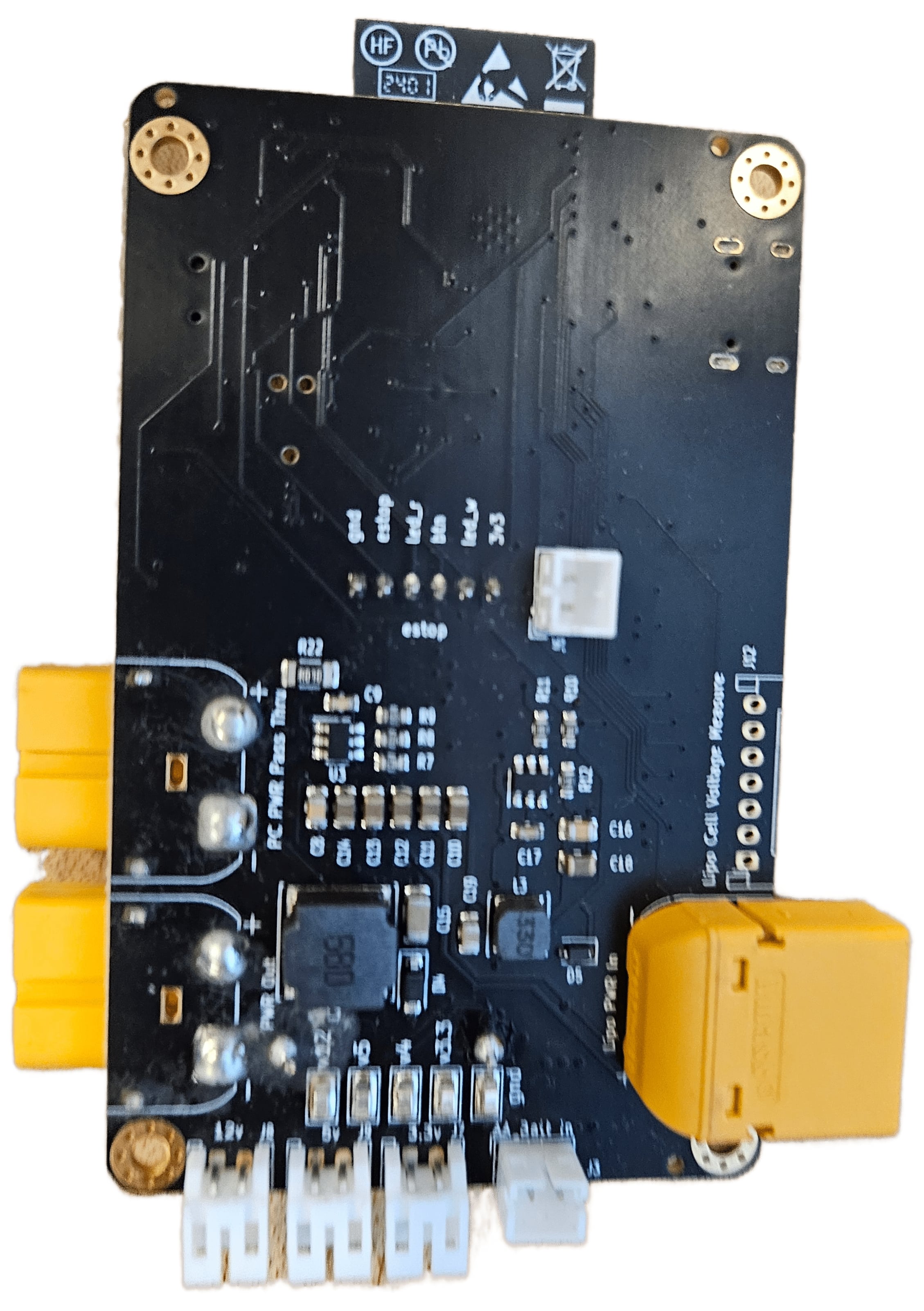
Documentation08 / ESTOP PCB Board
Wireless Bluetooth/Wi-Fi e-stop for high-current, multi-cell batteries.
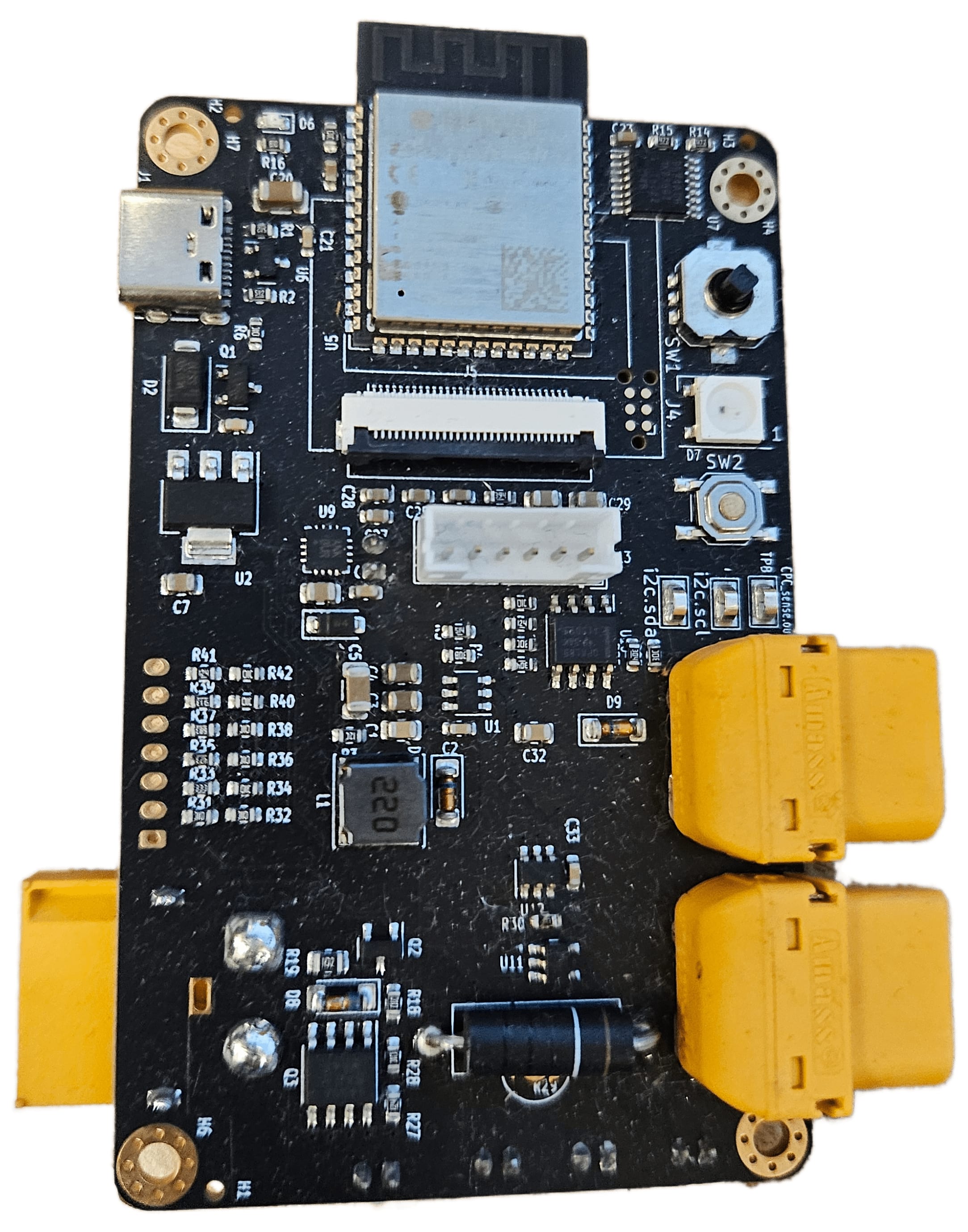
- MCU: ESP32-S3
- Power: USB-C & LiPo (7.4–28V, up to 20A) with 4.5V, 3.3V, 12V, and 5V regulators
- Battery: high-side MOSFET switch, voltage/current sensing, up to 6-cell monitoring
- UI: OLED display, directional switch, RGB LED, speaker (MAX98357A)
- Connectors: JST for 3.3V/12V/5V outputs, XT60 LiPo, 6-pin e-stop button
 01
01ESTOP PCB — back
Documentation09 / PCBBOT PCB Board
Robot driver board featuring an ESP32-S3 with camera support and student-proofing.
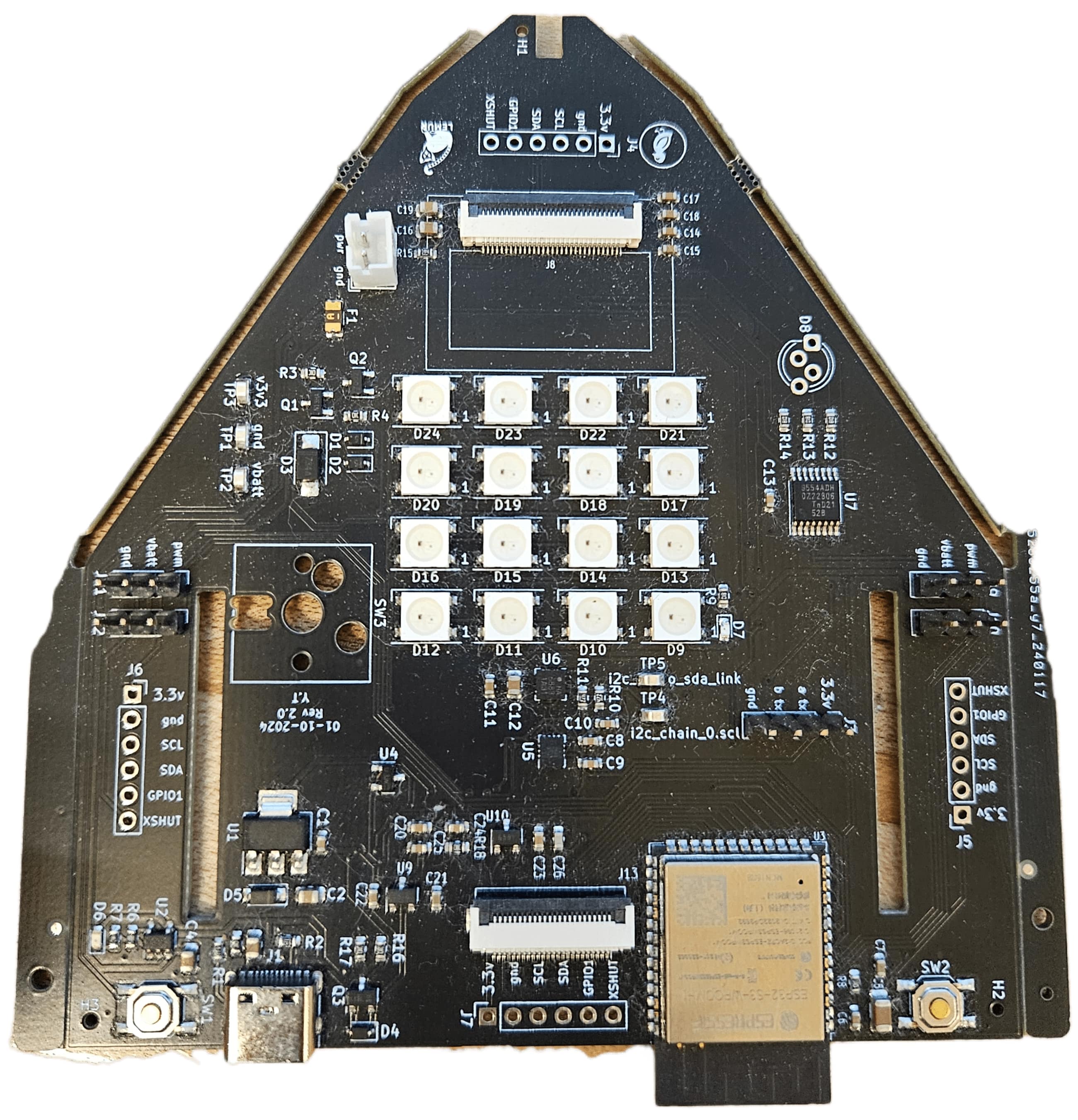
- MCU: ESP32-S3 with USB programming
- Power: USB-C & LiPo (3.7–4.2V) with series fuse, FET power gate
- Regulation: 3.3V supply plus 2.5V and 1.2V rails for the camera
- Charging: MCP73831 charger with yellow LED indicator via USB-C
- Sensors: 4× VL53L0X ToF array, 9-axis IMU
- UI/IO: OLED display, debug LED, touch input, IO expander for ToF control and RGB LED
- Actuators: 4 PWM connectors for servos
- Camera: OV2640 FPC camera
Special thanks to Ducky for the design and placement
10 / LiPo Charger Board
Reverse-protected single-cell LiPo charger.
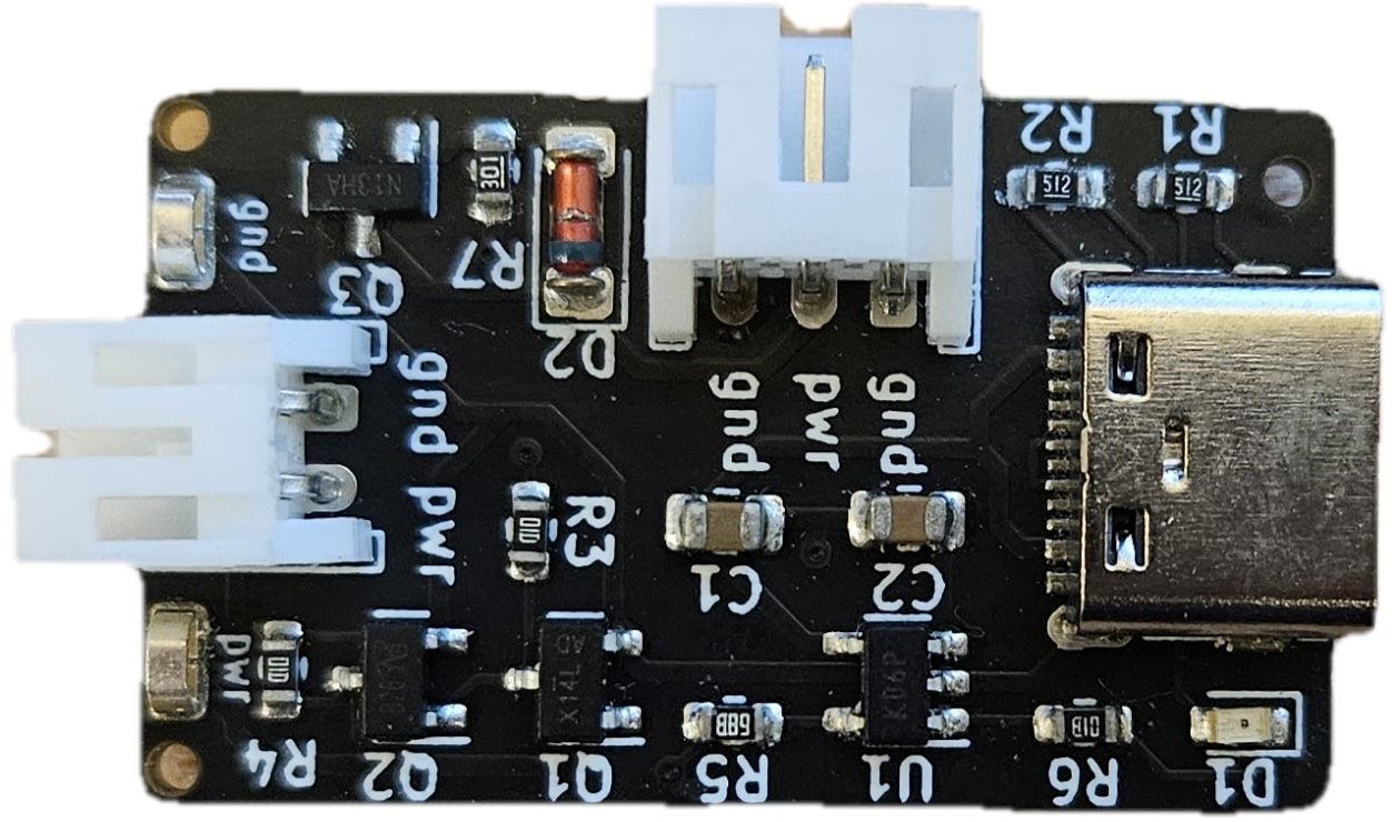
- Reverse-protected 1-cell LiPo charger
- Reverse-protected load port
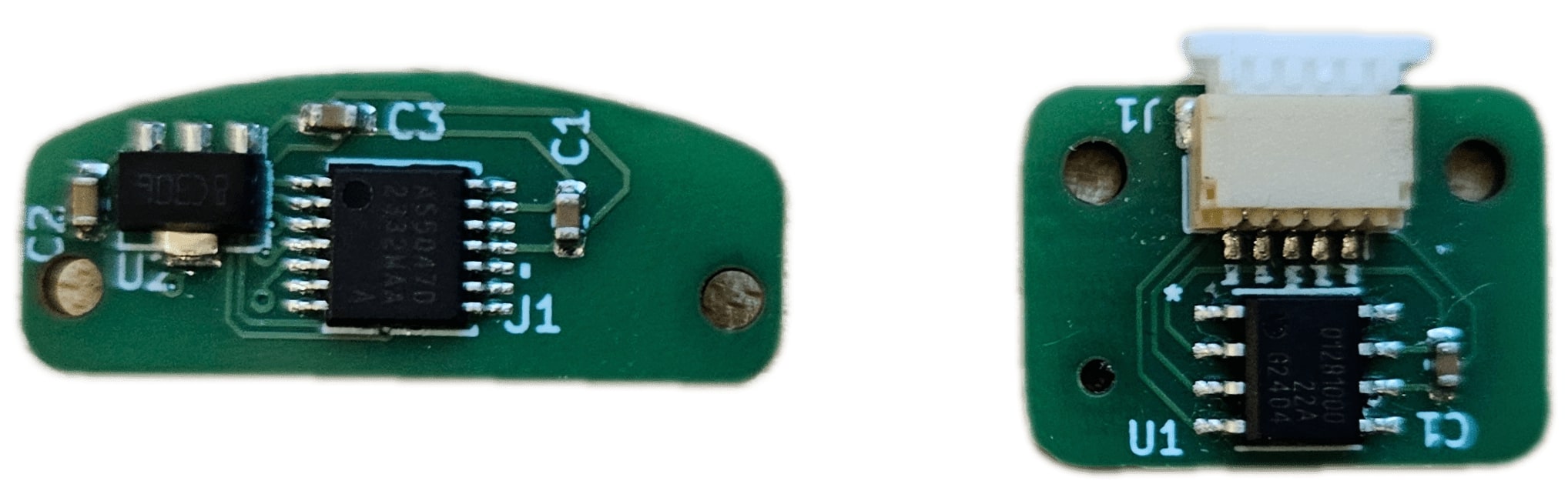
11 / Magnetic Encoder PCB Board
Ring-magnet encoder PCB boards compatible with CubeMars and MAB Robotics.
Acknowledgments
- Special thanks to Ducky for helping and reviewing the PCB designs.
Publications & related research
PolymorphicBlocks →